Motor Driver
H- Bridge:
• It is an electronic circuit which enables a voltage to be applied across a load in either direction.
• It allows a circuit full control over a standard electric DC motor. That is, with an H-bridge, a microcontroller, logic chip, or remote control can electronically command the motor to go forward, reverse, brake, and coast.
• H-bridges are available as integrated circuits, or can be built from discrete components.
• A "double pole double throw" relay can generally achieve the same electrical functionality as an H-bridge, but an H-bridge would be preferable where a smaller physical size is needed, high speed switching, low driving voltage, or where the wearing out of mechanical parts is undesirable.
• The term "H-bridge" is derived from the typical graphical representation of such a circuit, which is built with four switches, either solid-state (eg, L293/ L298) or mechanical (eg, relays).
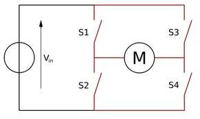
S1 S2 S3 S4 Result
1 0 0 1 Motor rotates in one direction
0 1 1 0 Motor rotates in opposite direction
0 0 0 0 Motor free runs (coasts)
0 1 0 1 Motor brakes
1 0 1 0 Motor brakes
• To power the motor, you turn on two switches that are diagonally opposed.
1 0 0 1 Motor rotates in one direction
0 1 1 0 Motor rotates in opposite direction
0 0 0 0 Motor free runs (coasts)
0 1 0 1 Motor brakes
1 0 1 0 Motor brakes
• To power the motor, you turn on two switches that are diagonally opposed.
The two basic states of an H-bridge.
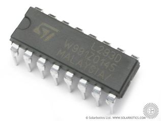
Motor Driver ICs: L293/L293D and L298
Motor Driver ICs: L293/L293D and L298
• The current provided by the MCU is of the order of 5mA and that required by a motor is ~500mA. Hence, motor can’t be controlled directly by MCU and we need an interface between the MCU and the motor.
• A Motor Driver IC like L293D or L298 is used for this purpose which has two H-bridge drivers. Hence, each IC can drive two motors.
• Note that a motor driver does not amplify the current; it only acts as a switch (An H bridge is nothing but 4 switches).
• Drivers are enabled in pairs, with drivers 1 and 2 being enabled by the Enable pin. When an enable input is high (logic 1 or +5V), the associated drivers are enabled and their outputs are active and in phase with their inputs.
• When the enable pin is low, the output is neither high nor low (disconnected), irrespective of the input.
• Direction of the motor is controlled by asserting one of the inputs to motor to be high (logic 1) and the other to be low (logic 0).
• To move the motor in opposite direction just interchange the logic applied to the two inputs of the motors.
• Asserting both inputs to logic high or logic low will stop the motor.
• Resistance of our motors is about 26 ohms i.e. its short circuit current will be around. 0.46Amp which is below the maximum current limit.
• It is always better to use high capacitance (~1000μF) in the output line of a motor driver which acts as a small battery at times of current surges and hence improves battery life.
• Difference between L293 and L293D: Output current per channel = 1A for L293 and 600mA for L293D.
Difference between L293 and L298:
• L293 is quadruple half-H driver while L298 is dual full-H driver, i.e, in L293 all four input- output lines are independent while in L298, a half H driver cannot be used independently, only full H driver has to be used.
• Output current per channel = 1A for L293 and 2A for L298. Hence, heat sink is provided in L298.
• Protective Diodes against back EMF are provided internally in L293D but must be provided externally in L298.
Speed Control:
• To control motor speed we can use pulse width modulation (PWM), applied to the enable pins of L293 driver.
• PWM is the scheme in which the duty cycle of a square wave output from the microcontroller is varied to provide a varying average DC output.
• What actually happens by applying a PWM pulse is that the motor is switched ON and OFF at a given frequency. In this way, the motor reacts to the time average of the power supply.