Basics
What is a Digital system?
In most general terms, this system’s behavior is sufficiently explained by using only
two of its states can be Voltage(more than x volts or less?),distance covered(more than 2.5 km or less?],true-false or weight of an elephant(will my weighing machine withstand it?) )
Note that although in every case, the all the intermediate states ARE POSSIBLE AND DO EXIST, our point of interest are such that we don’t require their explicit description. In electronic systems we mostly deal with Voltage levels as digital entities.
Assigning States
There is no specific fixed definition of logic levels in electronics. Most commonly used level designation is the one used in CMOS and TTL (transistor transistor logic) families:
Logic high –> designated as ‘1’
Logic low –> designated as ‘0’
GOOGLY: Why assign ‘0’and ‘1’ and not ‘a ‘and ‘b’, ’x’ and ‘y ,’cat ‘and ‘dog’?
ANS: Computational ease!
Where high and low are actually ‘higher’ and ‘lower’ with respect to a reference voltage level (ideally taken as 2.5V)
Number Systems in digital electronics
1. Binary: Only ‘0’ and ‘1’.
2. Hexadecimal: 0,1,2,3,4,5,6,7,8,9,A,B,C,D,E,F
Types of Digital Circuits
Combinatorial Circuits: In these circuits, the past states are immaterial and the output depends only upon the present state. Example logic gates .
Sequential circuits: In these circuits, the next state is completely determined by the past states. Hence these follow a predictable structure and essentially require a timing device. Ex. counters, flip flops.
Dec Hex Bin
00 0 0000
01 1 0001
02 2 0010
03 3 0011
04 4 0100
05 5 0101
06 6 0110
07 7 0111
08 8 1000
09 9 1001
10 A 1010
11 B 1011
12 C 1100
13 D 1101
14 E 1110
15 F 1111
Clock: Building block of a sequential circuit
A clock is simply alternate high and low states of voltage with time i.e. essentially a square wave. Important terms related to clock are its duty cycle and its frequency:
Duty cycle: It is the ratio of Th and Th+Tl D= Th/Th+Tl
Logic Gates: Building block of a combinatorial circuitry
These are essentially combinatorial circuits used to implement logical Boolean operations like AND, NAND, OR, XOR and NOT. NOT and NAND are called universal gates as any other gate can be formed using either of them!
Practical Circuiting Elements
Resistor:
A color scheme is followed to give the specifications of a resistor. The table for color code is shown below:
Resistor:
A color scheme is followed to give the specifications of a resistor. The table for color code is shown below:
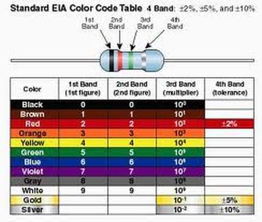
The 1st two bands specify the 2 digits of the resistor value whereas the 3rd band specifies the multiplier in terms of the power to which 10 is raised and multiplied to the 2 digits.
The tolerance tells the possible % variation of the resistor value about the value indicated by bands.
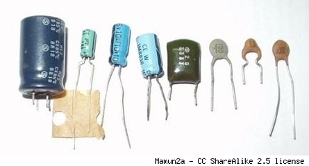
Capacitor:
The 2 types of capacitors we frequently use in circuits are ceramic and electrolytic capacitors. While ceramic capacitors do not have a fixed polarity; electrolytic capacitors should be connected in their specified polarities only else they might blow off! This polarity is usually provided on the side of the capacitors ‘corresponding leg.
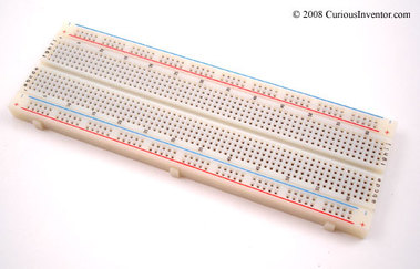
Breadboard:
This is the base used for setting up the circuit. This has embedded metal strips in it that form a grid of connections inside its body. This allows us to take multiple connections from a single point without any need of soldering/disordering as in PCBs. It is always a good habit to test the circuit on breadboard before making it on a PCB.
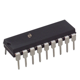
Integrated Circuits (IC)
ICs or Integrated Circuits are packaged circuits designed for some fixed purpose. An IC has its fixed IC name/number that can be used to get catalog of its functions and pin configuration. ICs come in various sizes and packages depending upon the purpose.
NOTE: Numbering scheme of IC pins will be explained in the lab session. Different ICs may have different number of pins.
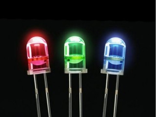
LED
LED (Light Emitting Diode) is frequently used to display the outputs at various stages of the circuit. It is essentially a Diode with the energy released in the form of photons due to electron transitions falling in the visible region. Hence normal diode properties apply to it. It glows only in fwd bias mode i.e. with p junction connected to +ve voltage and n junction to negative.
Diodes are essentially low power devices. The current through the LED should be less than 20mA.Hence always put a 220 ohm resistor in series with the LED.
Never forget that LEDs consume a significant amount of power of the outputs of the ICs (CMOS based).Hence it is advisable to only use them for checking the voltage level (high or low) and then remove them.